Filter Belt, Cloth Trackers
![]()
Operational check for Foxwell type Filter Belt Trackers
Standard Type
With the filter belt running and the air supply to the tracker turned on, pull back the valve lever on one side. This will cut off the air supply to the valve on this side causing the nip rollers to part and release the belt on the same side.
The belt should immediately move 1/2″ to 1″ (12 to 25) towards the opposite side. Release the valve lever and the nip rollers should come together again, pulling the belt once more into a central position.
Repeat this operation from the other side of the belt, with the same results, if nothing happens when both or either of the valve levers are pulled back, check that the rollers actually grip the belt when required. If not, check that the valves and rollers are set correctly (see sheet 3). If the rollers do grip the belt, but do not seem to have any effect, then increase the air pressure, in stages, up to the maximum of 40 p.s.i (3.0 kg/sq.cm).
If this does not have the desired effect, then increase the angle ‘ Z ‘ in stages, up to the maximum 20 degrees.
Note: angle ‘ Z ‘ should only be increased if the desired results cannot be achieved by increasing the air pressure.
Reverse Action Type
With the filter belt running and the air supply to the tracker turned on, pull back the valve lever on one side. This will allow air to pass to the valve on the opposite head causing the rollers on that head to grip the belt. The belt should immediately move 1/2″ to 1″ (12 to 25mm) towards the opposite side. Release the valve lever, and the rollers on the opposite head will part, thus releasing the belt. Repeat this operation from the other side of the belt, with the same results. If nothing happens when both or either of the valve levers are pulled back check that the valves and rollers are set correctly ( see sheet 3 ).if the rollers do grip the belt but do not seem to have any effect, then increase the air pressure in stages up to the maximum of 40 p.s.I. (3.0 Kg/sq. cm).
If this does not have the desired effect, then increase the angle ‘ Z ‘ in stages, up to the maximum of 20 degrees.
Note: angle ‘ Z ‘ should only be increased if the desired results cannot be achieved by increasing the air pressure
Instructions for Setting Headstock and Rollers
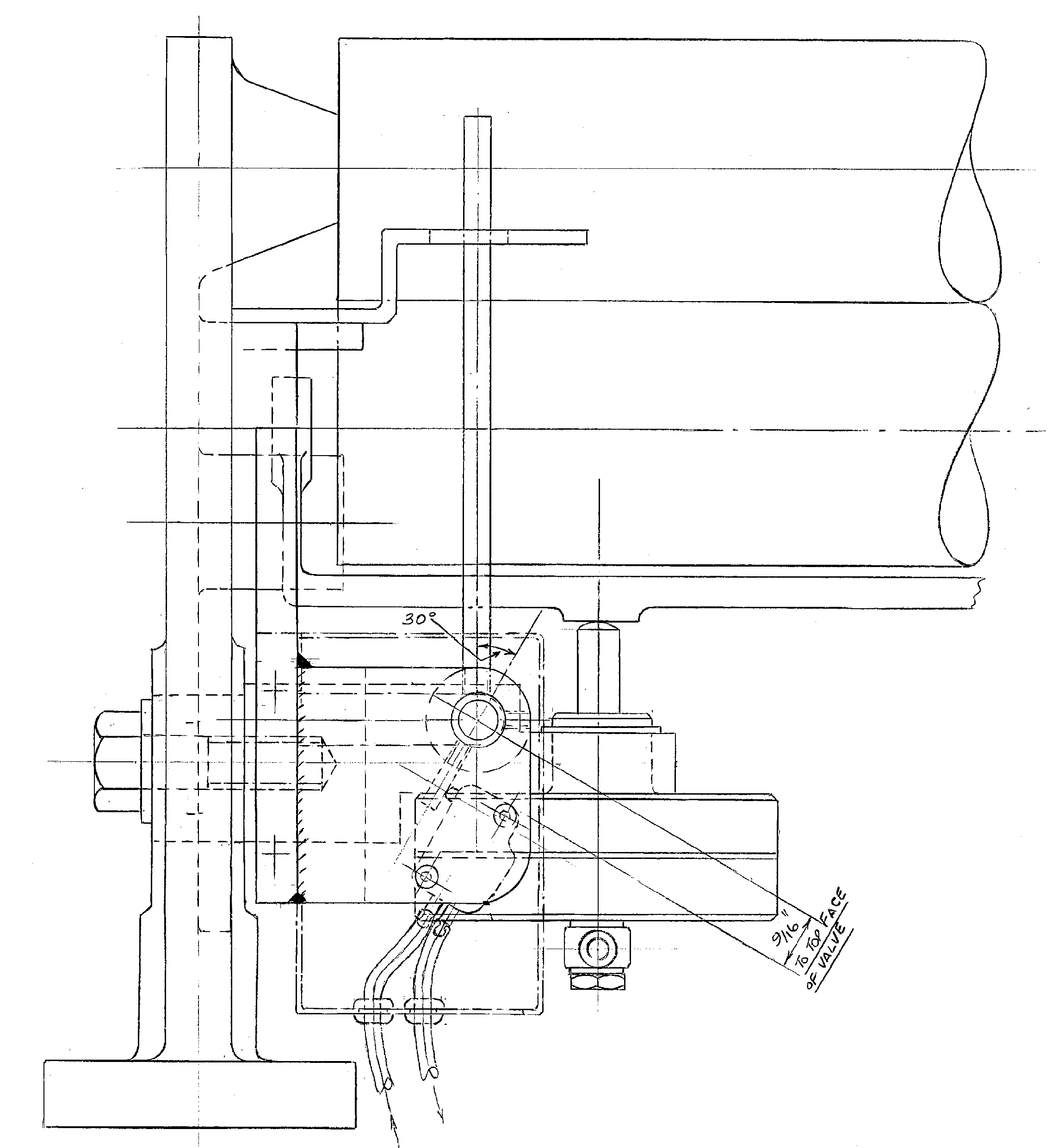
THE MOVABLE PRESSURE ROLLER ‘ G ‘ SHOULD BE SET AND ADJUSTED AS SHOWN
i.e. THE FACE OF ROLLER ‘ G ‘ ON THE SIDE NEARER TO THE HEADSTOCK BRACKET; Y SHOULD BE 1/16 ” (1.5 mm) AWAY FROM THE FIXED TOP ROLLER ‘ F ‘ WHILST THE OTHER END OF THE ROLLERS SHOULD BE IN CONTACT WHEN THE CRADLE ‘ T ‘ IS LIFTED BY HAND AND THE AIR SUPPLY IS TURNED OFF. THIS ENSURES AN EVEN ‘NIP’ OVER THE FULL ROLLER FACE UNDER WORKING CONDITIONS. TO ADJUST, SLACKEN NUT ‘ H ‘ AND SHIFT THE SPINDLE IN THE SLIDE. WHEN SET, TIGHTEN NUT ‘ H ‘ . WITH THE CRADLE ‘ T STILL RAISED BY HAND SLACKEN BOLT ‘ N ‘ AND POSITION THE VALVE HOLDER ‘ L ‘ SO THAT PLUNGER ‘ K ‘ IS BELT THICKNESS PLUS 1/8″ (3mm) AWAY FROM THE CRADLE ‘ T ‘ WHEN SET, RETIGHTEN BOLT ‘ N ‘ AND TURN ON THE AIR SUPPLY. CHECK BOTH ROLLERS ARE RUNNING FREELY
FIG 1 ‘Foxwell Type’ Pneumatic Belt Tracker Headstock
![]()
FIG 2 “Foxwell Type” PNEUMATIC BELT TRACKER HEADSTOCK (9″ SIZE SHOWN)
![]()
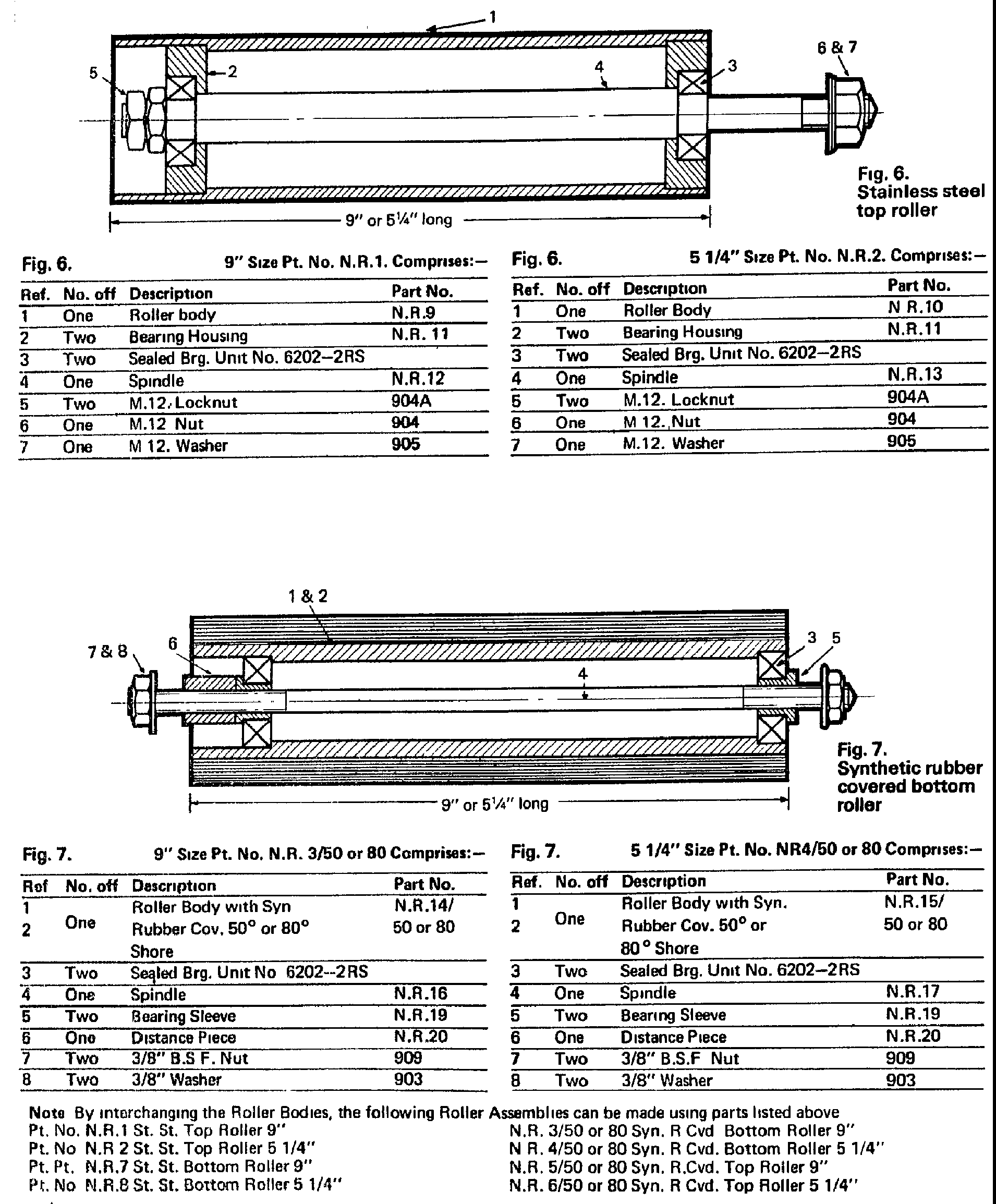
PARTS LIST FOR ONE 9″ HEADSTOCK ONLY AS SHOWN IN FIG.1 & 2.
No. OFF Part No. Drg.No. Mat’ l Description Remarks
ONE G.T.1 6704/3 ALUM.N HEADSTOCK BRACKET
ONE G.T.2 6705 ALUM.N CRADLE
ONE G.T.3 6705 ALUM.N DISTANCE TUBE
ONE 663 3127 ST.ST CRADLE SPINDLE
ONE ST.ST M12. NUT
ONE ST.ST M10 X 16 long SETSCREW
ONE ST.ST M10 WASHER
ONE N.R.1 6551 ST.ST TOP NIP ROLLER see sheet 7
ONE N.R.3/80 6551 SYN RUB BOTTOM NIP ROLLER see sheet 7
ONE A3.10663 ALUM.N VALVE HOLDER
ONE M.S M12 X 40 long SETSCREW
ONE M.S M12 WASHER
ONE A2.10666 ST.ST VALVE LEVER
ONE G.T.6 6711 ST.ST VALVE LEVER RETAINING PLATE
TWO ST.ST M6 X 12 long BUTTON HD SCREW
ONE ST.ST M12 WASHER
ONE A2.10575 D.F.E. VALVE see sheet 13/14
ONE VALVE SENSING MECHANISM see sheet 15
ONE M.S M16 X 30long SETSCREW optional
ONE M.S M16 WASHER optional
PARTS LIST FOR ONE 5 1/4″ HEADSTOCK ONLY AS IN FIGS. 1 & 2
EXACTLY AS LISTED ABOVE WITH THE EXCEPTION OF PARTS MARKED # THESE ARE
REPLACED BY: –
ONE 29A 383A BRASS CRADLE
ONE 663A 3127 ST.ST CRADLE SPINDLE
ONE N.R.2 6551 ST.ST TOP NIP ROLLER see sheet 7
ONE N.R.4/80 6551 SYN.RUB BOTTOM NIP ROLLER see sheet 7
Note :- Distance tube not applicable
Note :- THE ABOVE ARE PARTS LISTS FOR STANDARD TYPE HEADSTOCKS
FOR STRAIGHT FORWARD APPLICATIONS, SPECIAL SITUATIONS MAY
REQUIRE DIFFERENT VALVE LEVERS AND/OR NIP ROLLER MATERIALS
ALSO ITEMS MARKED * CAN BE SUPPLIED IN OTHER MATERIALS FOR
FILTER BELT APPLICATIONS (IN THIS CASE CRADLE AND DISTANCE TUBE
ARE ONE UNIT).
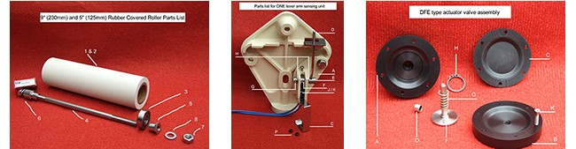
Roller Parts List
DFE Type ACTUATOR VALVE ASSEMBLY
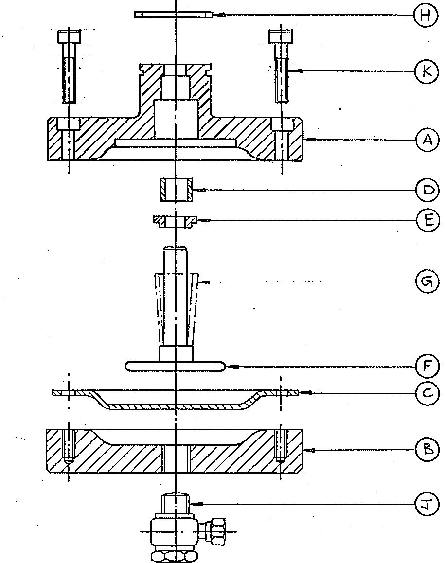
| No.OFF | PART No. | MATERIAL | DESCRIPTION | DRG No. | |||
| ONE | A | ACETAL | VALVE TOP | ||||
| ONE | B | ACETAL | VALVE BASE | ||||
| 0NE | C | NEOPRENE | DIAPHRAGM | ||||
| ONE | D | DU BRONZE | GLACIER BUSH | ||||
| ONE | E | ALUM,M | COLLET (optional) | ||||
| ONE | F | ALU/ST.ST | PLUNGER ASSEMBLY | ||||
| ONE | G | ST.ST | SPRING | ||||
| ONE | H | STEEL | EXT. CIRCLIP | ||||
| ONE | J | ALUM,M | 1/8” BSP BANJO FITTING | ||||
| SIX | K | ST.ST | M4 x 20 LONG STST CAPHEAD | ||||
VALVE SENSING MECHANISM
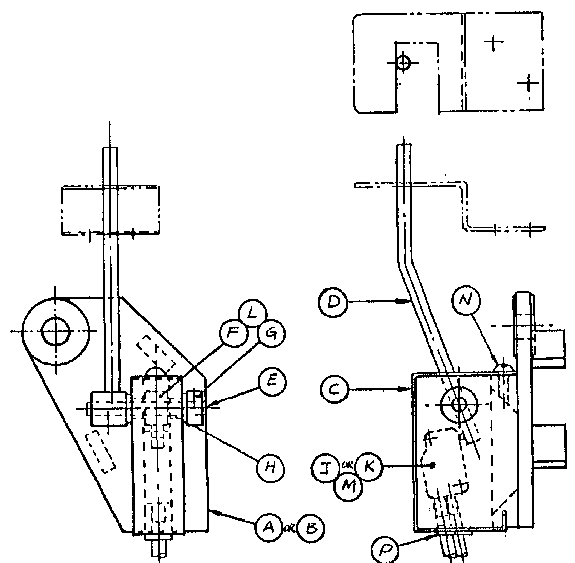
PARTS LIST FOR ONE SENSING UNIT |
||||||||
| REF | No. OFF | MATERIAL | DESCRIPTION | Drg No. /Part No. | ||||
| A or B | one | ALUM or CI | BRACKET | |||||
| C | one | ST.ST | COVER | |||||
| D | one | ST.ST | VALVE LEVER | |||||
| E | one | ST.ST | VALVE SPINDLE | |||||
| F | one | ST.ST | OPERATING COLLAR | |||||
| G | one | ST.ST | LOCATING COLLAR | |||||
| H | two | BRONZE | OILITE BUSH | |||||
| J | one | PNEUMATIC VALVE REVERSE (N/O) ACTION | ||||||
| or | TYPE S-3- PK-3-B | |||||||
| K | one | PNEUMATIC VALVE (N/C) ACTION | ||||||
| TYPE SO3-PK3 | ||||||||
| L | three | ST.ST | GRUB SCREW M5 x 5 LONG | |||||
| M | two | ST.ST | C/SUNK HD SCREW M3 x 20 LONG | |||||
| N | one | ST.ST | PAN HD SCREW M5 x 10 LONG | |||||
| P | two | RUBBER | GROMMETS TYPE No. 2 | |||||
| INSTRUCTIONS TO RESET VALVE LEVER | ||||||||
| 1 , REMOVE COVER ‘ C ‘ | ||||||||
| 2 , POSITION VALVE LEVER ‘ D ‘ TO THE INSIDE EDGE OF THE RETAINING SLOT AS | ||||||||
| SHOWN ABOVE. | ||||||||
| 3 , RELEASE THE OPERATING COLLAR ‘ F ‘ BY MEANS OF THE GRUB SCREW. | · | |||||||
| 4 , BRING THE PEG IN THE COLLAR INTO CONTACT WITH THE OPERATING BUTTON AND | ||||||||
| THE MICRO PNEUMATIC VALVE ‘ J ‘ OR ‘ K ‘ AND RE-TIGHTEN THE GRUB SCREW ‘ L ‘ | ||||||||
| 5 , CHECK FOR OPERATION AND REPLACE THE COVER ‘ C ‘. | · | |||||||